


AI introduces unprecedented challenges in data centers; not just in power, but in cooling, latency, deployment speed, and geography. These challenges carry through to all data center areas, or “subsystems,” to varying degrees.
These different subsystems often require tailored solutions in an AI data center, removing them from any semblance of a typical “uniform” design. At the same time, there are often different people responsible for each subsystem of a data center, so proper up-front planning and communication is critical. Let’s take a brief look at four key subsystems and the challenges they face with AI builds: the Entry-Point, Front-End, DC Interconnect, and Back-End Subsystems.
Entry Point
The Entry-Point subsystem is traditionally part of the data center gray space, supporting infrastructure by connecting outdoor cable to indoor-rated cable in the entry facility. Density demands from AI applications are driving increases of high fiber count cables coming into the Entry Point. At the same time, increasing power and cooling demands have further limited available gray space in the data center. This can cause complications for space utilization, cable management, and labor, resulting in speed of deployment being the most critical issue related to the entry point.
So how can data center operators mitigate this issue? Rapid and versatile installation is key; innovative splicing enclosures, splicing and interconnect trays, and preterminated solutions can be vital. These solutions unlock a modular approach to infrastructure, allowing for rapid and easy upgrades as needs evolve, and require much less time to install overall. For example, Leviton’s innovative line of STRATA™ solutions includes and entry point enclosure with the capacity to manage 6,912 fibers for splicing and interconnect with built-in cable management.
Front End
The Front-End subsystem is typically white space, and is the layer that handles traffic between users, internal resources, and external networks. Of the four subsystems, the Front End is least impacted by the addition of AI, buoyed above the waves that hit other subsystems by its established infrastructure. The Front-End Subsystem’s foundation has only received minor updates over the last five years. However, local code compliance is almost always a consideration when expansions occur on the front-end, especially when those expansions are in other geographic locations. Global solutions can alleviate this concern, allowing you to utilize the same infrastructure across locations where local codes differ slightly.
Data Center Interconnect
The DC Interconnect subsystem is part of the data center’s gray space, and consists of multiple cables or trunks running between the facility that connect buildings across the data center. Somewhat ironically, AI struggles with the capability the DC Interconnect subsystem was designed to deliver: connection over distance. An AI cluster on the back end is treated as a single system, housed in one location that then must spread itself over the rest of the facility. While this system can be broken into chunks to cover larger areas, physics still apply: the greater the distance covered, the more latency the network will struggle with.
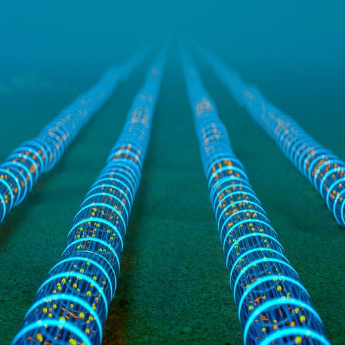
Hollow-core and multi-core fiber are emergent technologies that may provide relief. When compared to standard single-mode fiber, hollow-core can cover 2.25 times the area at the same latency footprint, making it an efficient solution for organizations looking to connect data centers at greater distances. Multi-core fiber, on the other hand, embeds multiple cores, typically four, inside one fiber cladding, offering high bandwidth capacity and increased density via transmitting multiple signals simultaneously. Both solutions come at a significant cost, so it’s likely that they won’t be considered economically viable for some time; however, both are worth keeping in mind as the technology progresses and industry conditions evolve.
Back End
Finally, there's the Back End; the subsystem that houses the AI cluster, and where AI implementation really changes the status quo. As the density of the system increases to accommodate the AI cluster, cable management and power become critical. The substantial power demands of AI technologies require data center operators to find ways to do more with their established power infrastructure.
The challenge of managing the increased density is one that data center operators are familiar with; doing more with less. This is where VSFF (Very-Small-Form-Factor) connectors like the MMC come in. VSFF connectors meet the need for higher density at connection points, while taking up less space than their MPO alternatives. Leviton's STRATA family of solutions has three times the port density using MMC compared to MPO connectors, with a capacity of 3,456 fibers per rack unit with MMC-16 connectors.
As for maximizing the potential of established power infrastructure, utilizing power more efficiently in the data center often boils down to cooling. Immersion cooling is an emergent technology wherein IT hardware and associated cabling are submersed in non-electrically-conductive, thermally-conductive fluids, offering almost-instantaneous heat dispersion for high-density networks. Leviton’s line of TORRENT™ immersion-ready solutions can facilitate the transition to immersion-cooling systems, as they are designed to perform reliably in dielectric cooling environments, maintaining signal integrity and resisting degradation even when fully submerged.
Get more insight on how AI will change the data center, as well as solutions developed specifically for AI and hyperscale data centers.
Like what you’re reading? Get more industry news and trends in our quarterly newsletter when it’s hot off the press.
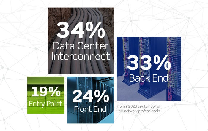
Leviton Poll
(multiple answers were allowed)
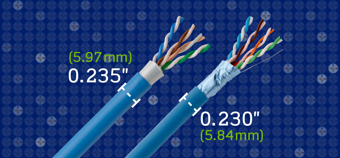
High performance in a small package — that’s the principle behind Leviton's small diameter Cat 6A cabling. RDT (unshielded) and FDT (shielded) are designed to maximize performance and return on infrastructure investment (ROII) where space is limited. Billed as the industry's smallest outside-diameter Cat 6A cables, Leviton RDT and FDT designs feature reduced outside diameters — as small as 0.230" (5.84 mm) — enabled by Leviton's proprietary precision twist technology and a cross filler-free design. The result is greater headroom performance with margins beyond the Cat 6A standard.
The unique design features of Leviton’s RDT and FDT Cat 6A cabling translate directly into savings. Let's break down how you can maximize your ROII with Leviton's most powerful small diameter Cat 6A cables.
Save Big on Retrofits
Leviton's RDT and FDT small diameter Cat 6A cabling is uniquely suited to facilitate upgrades, especially in places where space is at a premium. The reduced diameter enables easier routing through existing Cat 5e or Cat 6 pathways while delivering solid application performance with enhanced transmission quality. For warehouses, retail spaces, and commercial buildings, Leviton's small-diameter Cat 6A solutions help reduce installation and pathway costs by an estimated 10% per project.
More Sustainable
The reduced diameter and filler-free designs used across Leviton’s small-OD Cat 6A cable portfolio minimize raw material use, helping lower clients' overall carbon footprint while also reducing jobsite waste. Higher cable density, lighter weight, and more efficient packaging further support sustainability goals across manufacturing, transport, and installation.
Easy Deployment
Improve job site productivity with Leviton’s small-diameter Cat 6A cabling designed for high density installations. The reduced outside diameter, lighter weight, and increased flexibility of both RDT and FDT cables make them easier to pull and route through crowded pathways, helping installation teams work more efficiently while reducing labor, congestion, and overall project costs.
Whether you're designing with unshielded or shielded cabling, Leviton's small-diameter Cat 6A solutions are purpose-built to deliver performance, density, and ROII without compromising installation efficiency.
Leviton Network Solutions has achieved carbon neutrality across all facilities, a significant accomplishment and contribution to Leviton’s CN2030 initiative to hit company-wide carbon neutrality by 2030. We're constantly looking for new ways to push our sustainability efforts further — and a reflection of that is our new Leviton Zero Waste to Landfill (LZWL) program.
Our LZWL program is designed to help facilities pro-actively improve Waste Management internally and externally. Our employees begin by forming a Green Team, setting goals, and reviewing established processes and procedures, as well as engaging and educating current and new employees on best practices for waste management. Improvements are then made across all spaces: factory floors, office levels, supply chain, and packaging are all evaluated, and new initiatives are implemented to reduce landfill contributions.
After thorough review, approved facilities are awarded based on waste diversion from landfill parameters and certified for four years. Once awarded, each certification is followed with annual checks before applying for reapproval.
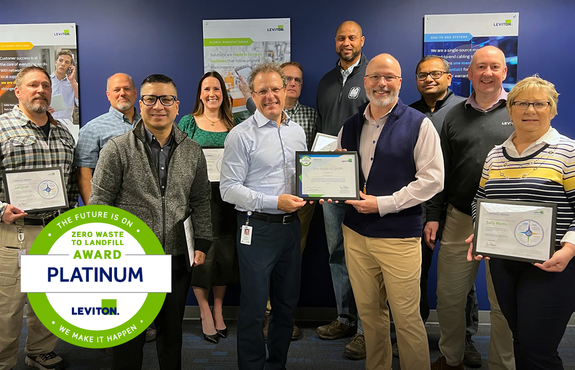
Our New Holland Team recently achieved our highest distinction: the Platinum Zero Waste to Landfill award for achieving >98% waste diversion plus best-in-company controls. We’re also proud to share that several additional locations are now certified through our Zero Waste to Landfill program, with more on the way. This momentum reflects the teamwork and dedication driving meaningful sustainability progress across our organization.
Explore Leviton’s sustainability initiatives, as well as the wider CN2030 program.
Consolidation points (CP) are optional additional connections allowed within the horizontal cabling of a structured cabling installation. CPs are typically used to avoid unnecessary recabling, either when changing cable types in the middle of a horizontal link, or in office areas as open office furniture is reconfigured. If implemented correctly, they can be an effective way to avoid hours of rework.
10 tips for using consolidation points:
Get more tips on deploying consolidation points, misconceptions about consolidation point design and usage, and why certain products are not useful as components of a consolidation point design.

Q: Does tight cord bend radius affect patch cord durability?
A: An end user made a comment they were having to replace patch cords, sourced from a competitor, in all of their Wireless Access Points (WAPs) every couple of months. This user suspected the problem with the cords was due to the very tight cord bend radius near the plug end going into the WAP. While we did not think cords held at tight bend radius over time would cause any performance degradation on our high-quality Leviton solutions, we did not have specific data to support our belief; so we initiated a study.
A channel was created—horizontal cabling with a Cat 6A Leviton High-Flex H6A10 patch cord at each end. Patch cords would be initially tested in their relaxed state and then these cords would be set up with 180 degrees of the tightest allowable bend radius at each end of the cord. The test was scheduled to run for 250 days, with channel and patch cord testing performed at intervals throughout the test duration.
After initial testing of the cords in their relaxed state, patch cord bend radius was maintained for the duration of the test, by wrapping and tying the cord ends with 180 degrees of bend, around spools sized for the minimum allowable bend radius for the cords being tested. Patch cords were tested in-channel, then removed from the channel, and each tested individually. Then they were placed back into the channel until the next round of testing. The bend radius shown was strictly maintained throughout the entire 250-day test.
Testing that spanned over eight months indicates no significant performance degradation over time, when Leviton High-Flex H6A10 patch cords are held in the tightest allowable bend radius. Users may proceed with confidence when using these patch cords, even in applications where there is very limited space at the port opening. Explore Leviton High-Flex patch cords.