Loading...
Selected products added to your list. To view the list, Click here

CrossTalk Newsletter

Your Source for Industry News & Insight

CrossTalk Newsletter

Evaluating Options for Fiber Termination

In the ever-evolving landscape of network connectivity, selecting the appropriate termination method for fiber optic installations is crucial. Whether you’re a seasoned installer or a newcomer to the field, understanding the nuances of termination techniques can significantly impact your project’s success. Let’s break down the three termination techniques that are most commonly used in networks like yours.

Epoxy and Polish Connector
With field polishing, contractors attach using an adhesive and individually polish each connector. While once a very popular method, epoxy/polish introduces many downsides. It can be very time-consuming and requires consistent replenishment of consumables. Since this is craft sensitive, it is more difficult to provide a consistent end face quality. This polishing method can also be difficult to achieve lower insertion loss values and the 55 dB return loss requirement for single-mode UPC connectivity. If polishing is the selected method, it is recommended to invest in an optical time domain reflectometer (OTDR) to measure optical reflectance. Tier 1 Certification (via an Optical Loss Test Set) may still be required when submitting for warranties, and some technicians don’t use an OTDR, resulting in poor reflectance found when problems arise.

Mechanical Splice Connector
Traditionally, mechanical connectors were considered a temporary “quick fix” solution. However, the technology in mechanical connectors has advanced over the years, and the advantages have made them a higher quality long-term solution. With mechanical connectors, the end-faces are factory-polished and highly controlled, leading to better insertion loss, better return loss and less overall labor. However, this termination option will have a higher material cost than field polished connectors and will require a precision cleaver.

Fusion Splicing
Unlike mechanical splicing that only aligns and does not physically join fibers, fusion splicing provides a permanent fusion connection between fibers. Typically, fusion splicing has a loss of 0.1 dB or less, while mechanical splicing typically has higher insertion loss of between 0.2 dB to 0.50 dB. Although mechanical splices can be valuable for certain applications, the fusion splicer can estimate the loss of the fusion splice, reducing the uncertainty of mechanical splicing or field polishing.

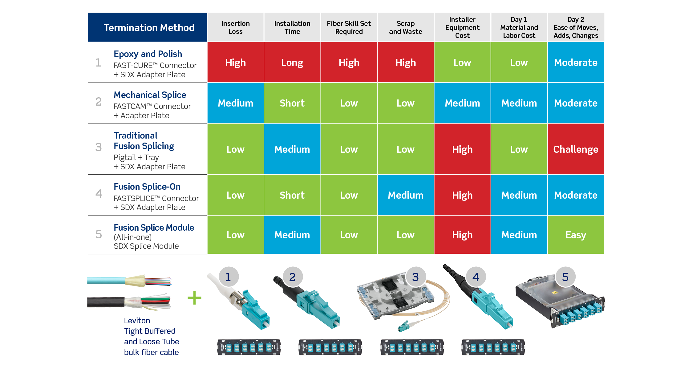
For these reasons, coupled with the steady decrease of fusion splicer prices, splicing pigtails, splice-on connectors (SOCs), and splice modules have become popular termination options for the enterprise. For a more in-depth comparison of these termination methods, check out the table below, which compares different termination approaches using Leviton solutions, including epoxy/polish connectors, mechanical splice connectors, and several fusion splicing options. The table compares termination options across six categories, from loss performance to skill set to material and labor costs. Learn more about Leviton Network Solutions’ fusion splicing offerings.


Subscribe Today

Like what you’re reading? Get more industry news and trends in our quarterly newsletter when it’s hot off the press.

Leviton Poll

How are you terminating your fiber today?

Expert Data Center Design: Turning Possibilities into Plans

As networks become increasingly complex, organizations like yours need partners that will provide more than cable and connectivity. Our data center design experts work closely with you to understand your needs, provide an optimal plan for deploying structured cabling solutions, and create a complete bill of materials. They’re ready to help through remote or on-site analysis and can deliver custom product designs that meet your specific network requirements. Moreover, using our Optical Link Verification Tool, Leviton experts can provide customers with a snapshot of how any given topology system will outperform the industry standard using Leviton data center cabling systems.

Of course, it’s one thing to say that we have those capabilities; it’s another entirely to demonstrate them. Let’s examine a couple of customer success stories that showcase the Leviton difference.

GLOBAL CLOUD-BASED DATA CENTER CUSTOMER
The data center design team played a vital role in assisting a major cloud-based customer relationship management firm. The customer required a unique leaf/spine configuration that was an entirely new topology for the company. To ensure the customer was getting the full benefit from their network, a member of the Leviton team arrived on site to get a first-hand look. He created a mockup of the network for the customer, and it was deployed shortly after. Since installation, the customer has replicated the Leviton-recommended design in four other facilities around the world.

GLOBAL COMMUNICATIONS CUSTOMER
The team also aided a high-profile global communications company with a leaf/spine topology incorporating a SAN. A member of the Data Center Design Team traveled to the site to obtain a clear understanding of the customer’s requirements. He compiled an in-depth design proposal and a customized bill of materials that precisely outlined the customer’s connectivity needs. The proposed layout is currently being installed and will include Leviton flat and angled e2XHD patch panels, MTP® cassettes, and MTP fiber trunks.

These success stories and others illustrate a key competency of ours: our teams meet you where you are, work with you towards a solution, and take your ideal data center design from possibility to reality.

With the purchase of our products and services, our data center design team provides:

  • Conceptual drawings
  • Rack layout
  • Line drawings
  • Elevation drawings
  • Channel polarity
  • Bill of materials


Get started configuring your optimal data center design today.

News You Can Use

The Standards Report: The latest industry changes and what they mean to you. Download Now

US Only: Structured Cabling and Smart Homes - With the proliferation of smart technologies and bandwidth hungry devices, a robust structured cabling system is more important than ever for the modern home. In our webinar “Better Connections: Maximizing the Value of Your Smart Home Investment,” learn about residential connectivity trends, networking best practices, and the latest Leviton Connected Home infrastructure solutions. Watch the Webinar

Yesterday’s News: The first private ethernet network was officially launched in 1976 at the Xerox Palo Alto Research Center (PARC); the same place where creators Robert Metcalfe, David Boggs, Chuck Thacker, and Bob Lawson developed the first ethernet cable. In the same year, Metcalfe and Boggs produced their first academic paper on the subject, titled “Ethernet: Distributed Packet Switching for Local Computer Networks.”

Tech Tips: Unlock Extended Distance

It is possible to install functional channels at distances beyond 100 meters with twisted-pair copper cabling – however, variables that impact the channel functionality must be accounted for.

Conductor Size:
Larger conductors offer less insertion loss and lower DC resistance, allowing signals to travel further and DC power to arrive with sufficient strength at longer distances to connect and power a remote device.

Twist Rates:
While tight twists have a positive impact on crosstalk suppression, it has the opposite effect on insertion loss. Fewer twists equates to less distance a signal must travel to get to its destination.

Dielectric Cable Properties:
A cable’s component materials, such as waterblocking gels and insulation materials, can change the insertion loss characteristics of a cable and need to be optimized for extended distance support.

Leviton’s ATLAS-X1™ SST Global MILLENNIUM™ cabling system now guarantees 140 meter support for 2.5 Gbps Ethernet, 155 meter support of 1 Gbps Ethernet and 200 meter support of 10 Mbps Ethernet.

Learn more about ATLAS-X1™ SST.

Ask The Experts

Q: I don’t have a factory; when would I use Industrial Ethernet cable?

A: Industrial Ethernet (IE) cable can be used in any area where you have to be concerned with environmental stressors. Such stressors can include consistent flexing (such as a jet bridge, a robotic arm), abrasion issues (such as rubbing against a moving part), rotational effects, or even having chemical emissions nearby (for example, propane burning). Our IE cables also tend to have wider installation and operating ranges which come in handy for applications such as frozen and refrigerated warehouses for food and pharmaceuticals. While it is called “Industrial Ethernet,” it’s really a heavy-duty cable for unusual applications.

Learn more about industrial connectivity.

Drop Us a Line

Ask our experts or share an idea for an upcoming issue.
We want to hear from you!